![]()
![]()
![]()
![]()
![]()
![]()
![]()
![]()
![]()
![]()
![]()
![]()
![]()
![]()
![]()
![]()
![]()
![]()
![]()
|
|
|
|
2004 Instrumentation Upgrades
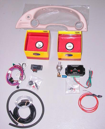
Early in 2004, with development on the Kenne-Bell supercharger kits for '99/'01 Cobras nearing completion, I decided it was time to install a pair of gauges to provide what most ratchet heads consider vital information for any forced induction application: fuel pressure and vacuum/boost levels. When I moved the car to forced induction, I would need to keep an eye on both. After looking at the offerings from all of the major and several of the minor automotive instrument manufacturers, I settled on a couple of 2-1/16" Auto Meter electronic gauges in the company's Phantom series. Although some aren't fond of Auto Meter products, and a few even allege that Auto Meter instruments aren't accurate or aren't reliable, I've always enjoyed excellent performance and reliability from the Auto Meters I've used over the years (as opposed to a couple other brands that I could name). There are several options available for mounting 2" gauges in an SN95 Mustang when installing only a pair of them. My two primary considerations for the mounting arrangement were (1) that the gauges be close to my line of sight while I was focused down the road, and (2) that the gauges integrate well into the car's interior. I thought the A-pillar arrangements looked extremely cool, but I feared they were too far out of my sight line. Dash pods aren't as elegant, and they require you to shift your eyes right a bit, but I probably would still have opted for a dash pod if Auto Meter hadn't made an instrument cluster bezel available for the car. Given my two main concerns, the instrument cluster bezel was my obvious choice. There's a reason why traditional gauge placement directly below the driver's view of the road continues to dominate automotive instrumentation: it works best. And with respect to integrating the new gauges into the interior, you just can't beat the Auto Meter bezel once it's been painted in a color that matches the rest of the interior. Since the Auto Meter instrument cluster bezel is available in only black, I needed a good quality paint that would match my car's parchment dash, but finding the right color paint for the bezel turned out to be tougher than I had expected. I left auto parts stores and home improvement centers several times with the wrong color before I discovered Late Model Restoration. No matter what color you need, that place has it, and there's no guesswork required. In the photo below, the bezel has already been painted with several coats of 50Resto's parchment color lacquer paint. The beauty of lacquer is that it can be built up quickly in layers, because it dries from the inside out (unlike enamel, which dries from the outside in), and lacquer dries extremely fast.
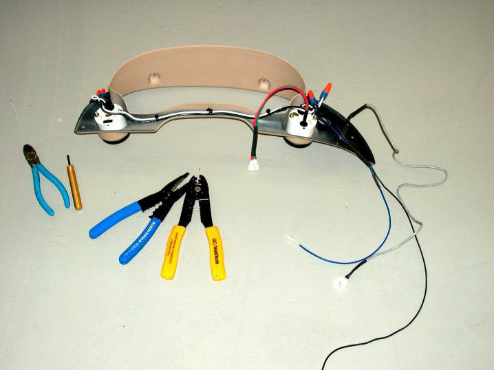
The gauge on the left in the above photo is the Auto Meter model 5776 electronic vacuum/boost gauge. This little baby contains a programmable over-boost monitoring circuit and warning light as well as a max boost memory circuit with playback function. Below the gauge are its sending unit, wiring harnesses, tubing, etc. The gauge on the right above is the model 5764 electronic fuel pressure gauge, which came with a separate memory module containing min/max fuel pressure memory circuits and playback features. Below this gauge are its sending unit, memory module, harnesses, and miscellaneous additional parts. I suppose very few wanted to spend the extra $100 for the 5764 over the 5763 in order to get the memory module, or maybe they just weren't up to tackling the more complicated installation. Whatever the reason, the 5764 wasn't exactly a hot seller, so it is no longer available. Fortunately, I was able to scoop up one of the last available units before they disappeared from the marketplace. Besides the Auto Meter components, the above photo contains a couple of additional items that I picked up to complete the gauge installation. First, the vacuum/boost gauge kit comes with only the clear tubing you see above for connection of its sending unit to its vacuum line Tee fitting. I wasn't keen on the way that arrangement would have looked, and I feared it would have been far too susceptible to damage, so I picked up some rubber vacuum line to slip over the clear tube as a sleeve to provide improved protection and a more finished appearance. Second, I had heard about clearance issues related to connecting the fuel pressure sending unit vertically to the Schrader valve on the passenger side fuel rail, so I picked up a right-angle adapter, which is already attached to the sending unit in the above photo. Editorial Comment: You may have heard it said that mechanical gauges are more accurate than their electronic counterparts. This is a load of dung originated and perpetuated by the Flat Earth Society, whose members do not yet fully grasp the concept of fire, much less electricity. All the calibration test results that I have seen support my contention that good quality electronic gauges are every bit as accurate as mechanicals, if not more so, so don't delude yourself into believing mechanicals are inherently more accurate. They aren't. Being cheaper is their one and only advantage over electronic units. By all means, install mechanical gauges if you need to save a few shekels on your instrumentation. Installation of mechanicals can be a taxing experience, but they ARE significantly less expensive than decent quality electronic gauges. The photo below shows the back side of the Auto Meter bezel after I had mounted the new gauges and the illuminated "valet" button for Taz's theft alarm system. For the gauge installation, I picked up an assortment of polarized, snap-together Molex connectors and a Molex crimp tool. I was so impressed with them that also I retro-fitted these connectors to my console-mounted MB+ fuel trim selector switch and LED's, since I had the console open anyway. These connectors are much better than the bullet connectors I had originally used. You can see Molex connectors installed on a few of the cables in this photo.
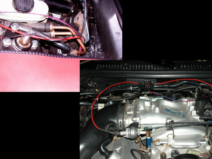
Mounting the gauges in the bezel was the easy part. The real work remained to be done. First, the sending unit wires had to be pulled through the firewall. I decided to use a large existing porthole and grommet in the firewall, rather than cut a new hole for a half-dozen wires. Adding the wires from the sending units to the bundle of wires already packing the grommet wasn't easy, but it was doable. (Thank goodness for silicone plumber's grease!). I even had the presence of mind to pull an extra wire through the firewall while I was running the sending unit wires. I figured this fish wire would come in handy when the supercharger kit arrived. (This premonition later proved correct.) I didn't bother tidying up the engine bay side of this installation, since I knew I'd be tearing it up again after the Kenne Bell kit arrived, so I just ensured that each harness had ample length and was out of harm's way for the time being. (See below.)
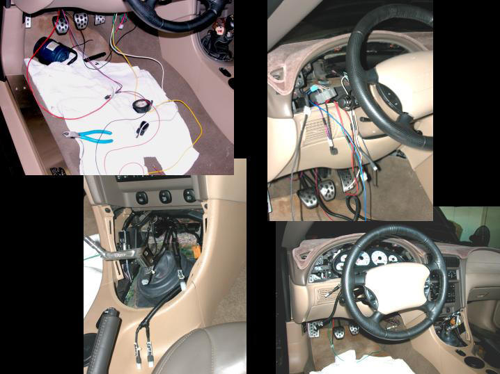
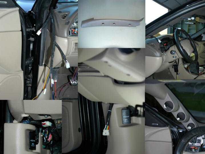
The cabin side of the gauge installation was an entirely different matter. I wanted the interior to look like Ford had shipped the car from the factory with the additional instruments when I had finished with that end of the project. I referenced the Ford maintenance CD-ROM to determine exactly where to tap into the car's existing electrical circuits, and then began tearing the dash and console apart. The composite graphic below contains a few photos of the work in progress. A project such as this can be somewhat intimidating for those unaccustomed to working with electrical circuits, and mistakes can damage pricey components. If you're not experienced at reading wiring diagrams or splicing and terminating wires, you might want to find someone who is to help you with this sort of work.
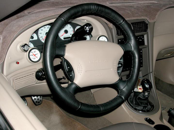
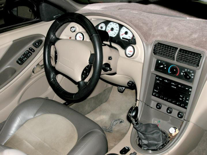
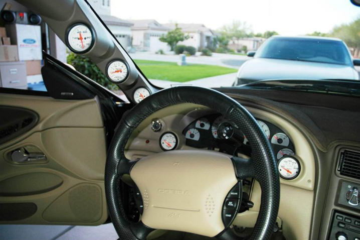
I had decided that, in addition to the new gauges, I was going to need a serious shift light - something considerably more attention-grabbing than the rather inconspicuous little incandescent lamp I had mounted in the instrument cluster bezel when I had installed my MB+ unit. (One can hardly afford to over-rev a stock bottom end that is not just pushing the envelope, but kicking the ever-loving snot out of it.) I initially purchased and installed an Auto Meter Super-Lite to serve as my new shift light. Like all Auto Meter products I've used, the Super-Lite functioned perfectly, but it just didn't aesthetically work in Taz's interior, so I swapped it out for a VDO shift light that works better with the car's other interior appointments, as well as my personal preferences. With the VDO mounted on the steering column and the column tilted down to its normal driving position, the shift light is perfectly ringed by the face of the factory tach. Here are a couple photos of the completed 2004 instrumentation project ...
Just in case you're curious - or not - about where the memory module for the fuel pressure gauge ended up, I fabricated a couple brackets for the module from some galvanized stock and mounted it face-down beneath the dash, centered under the steering column. With the memory module installed this way, it's completely out of sight unless you're lying on your back under the dash, but its recall and reset buttons are within easy reach from the driver's seat. Here's a link to a PDF file containing details of the gauge installation that you may find useful if you're pursuing a similar project. The file contains circuit and connector information for the tie-in points I used. 2004 gauge installation notes (PDF) Editorial Comment: Why not install digital gauges, especially considering their current popularity? Short answer: I personally prefer analog. Long answer: This is not the first time in automotive history that digital gauges have been the rage, and from what I've seen, the same shortcomings that resulted in the previous demise of digital automotive instrumentation are still present in the current crop. First, unlike analog gauges, digitals are extremely difficult to read under various lighting conditions, which is not a good thing when you need to obtain critical information as quickly and easily as possible. Second, with a digital readout, all you are presented with is a raw number without any context. I'm so old that I can recall when digital watches were all the rage. They eventually fell from grace for exactly the same reasons. For me, a digital watch or automotive gauge possesses the uncanny ability to simultaneously provide both more and less information than I either need or want. By more, I mean that I really don't care to know that my fuel pressure is exactly 42.65 psi. All I really want and need to know is that it's between 40 and 45. By less, I mean that a disembodied number provides me with no frame of reference, i.e. no information about whether the displayed value is high or low, good or bad. I cannot generally read the exact value indicated by an analog gauge, but I do not care to. I am much more interested in the instantaneously conveyed PROPORTIONAL information. Both the pointer and dial are always readily visible at a glance, regardless of the prevailing lighting conditions, and I can instantly determine whether the indicated value is high or low, based on the pointer's position relative to the entire scale. This enables me to quickly assimilate the data presented by analog instruments, which is important to me, because whenever I'm looking at the gauges, I'm NOT focused on the road. One cannot instantly process the information presented by digitals. TECH TIP: Prudent application of colored vinyl electrical tape to the bezels of analog gauges will enable you to instantly determine whether or not their needles are indicating safe values without even focusing on them. Home Depot sells a nice blister pack containing 5 different colors of tape for just a couple bucks. I employ this trick whenever I go to the track and need to spend an absolute minimum amount of time scanning my instruments - white tape for the sweet spot, yellow for the periphery of the acceptable zone, and red for "Houston, we've got a problem." This works great, and the tape can later be easily peeled off, although I normally leave my white tape in place all the time.
2009 Instrumentation Upgrades
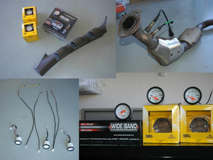
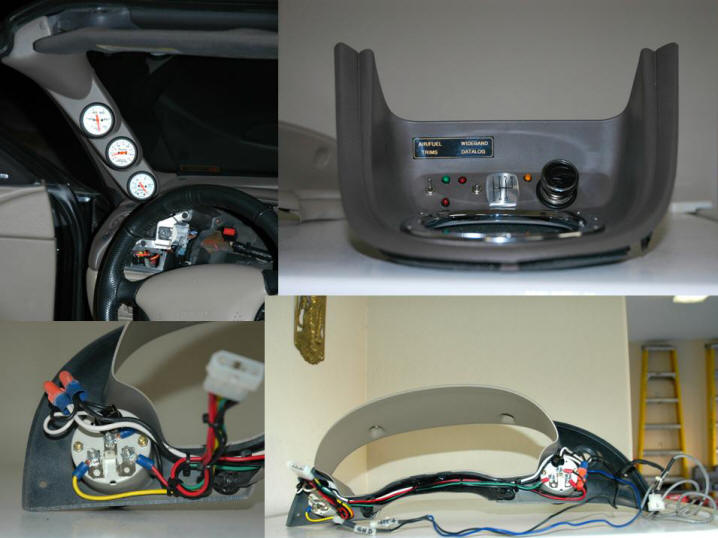
For 2009, I further augmented the Cobra's instrumentation by adding a wideband gauge to enable monitoring of the car's A/F ratio and a pair of temperature gauges to keep tabs on engine oil and intercooler fluid temps. Since I had previously installed gauges from Auto Meter's Phantom series, I selected temperature units from the same series, the 5737 and 5747, both of short sweep design. Naturally, I wanted a wideband A/F gauge that resembled the Phantom series as closely as possible, and the Dynojet Wideband Commander Model 15-7002 was a nearly perfect match. However, unlike the new temp gauges, the Wideband Commander was a 270-degree full sweep gauge, similar to the two Auto Meter gauges I had installed in 2004. (See the bottom right panel of the composite below for a look at the faces of the three new instruments.) I decided to replace the full sweep gauges in the instrument cluster bezel with the two short sweep temperature gauges, so I could group all the full sweep units together in a new instrument pod. For a triple gauge pod, my options were somewhat limited: either a dashtop pod or an A-pillar pod. Strictly speaking, there is a third solution, but few ever opt for it, because it requires the replacement of a component in the center stack with a 3-gauge DIN panel. Not being especially keen on dispensing with anything in the Cobra's center stack, I didn't consider that a viable option for myself, and between the two realistic alternatives, I was leaning toward the dash pod until my buddy Jim installed an Auto Meter 3-gauge A-pillar sleeve in his Lightning. After scanning his gauges while seated behind the Lightning's wheel, I adopted a much more favorable opinion of A-pillar instrumentation, and I eventually decided on an A-pillar solution for Taz. Auto Meter once again got the nod for the gauge housing, because the company offered a full shell that completely covered the Cobra's OEM trim piece, providing a seamless, factory-looking result. Some other A-pillar solutions look okay from the driver's seat, but are terribly ungainly looking when seen from the front of the car. Of course, I needed to paint the new gauge shell after it arrived, because like all Auto Meter pods and panels, this part was available in any color I wanted, as long as it was black. Having learned my lesson regarding paint matching during the car's previous gauge augmentation project, I didn't bother with trying to find the correct color at a local vendor. I browsed directly to the website of Late Model Restoration and ordered up a couple cans of dark parchment spray paint to duplicate the original A-pillar color. Along with the three new gauges, the upper left panel of the composite below shows my new A-pillar shell after I had painted it with multiple coats of 50Resto's dark parchment color vinyl paint. I was pleasantly surprised to discover that this vinyl paint dries nearly as quickly as the company's lacquer. Great stuff! If you ever consider installing a Dynojet Wideband Commander, you should be aware that the installation of this gauge is nontrivial. Part of the difficulty arises from some required exhaust welding, because the bung for its Bosch wideband oxygen sensor must be grafted into the exhaust system somewhere ahead of the catalytic converters. Everything's a tight fit down there, so choose your spot carefully if you decide to install a wideband on your own car. After a preliminary clearance check with the mid-pipe still installed on the car, I decided to mount my own sensor next to the front factory oxygen sensor on the right down-tube of the Cobra's mid-pipe, and the folks at Cliff's Welding were kind enough to blow a hole in the pipe and weld the bung in place for a very nominal fee while I waited. The upper right panel of this composite shows the new bung and sensor after installation.
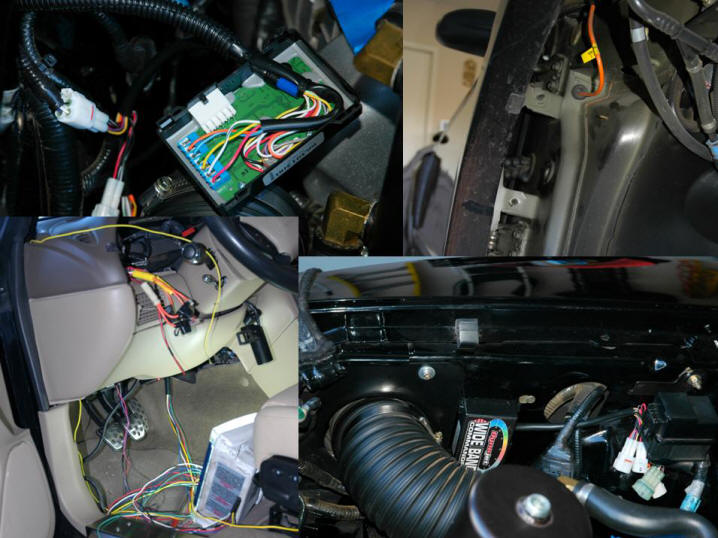
The photo at the bottom left of the composite above is a shot of the three gauges that I had decided to install in the new A-pillar shell after they had been configured with short Molex-terminated pigtails to enable their quick removal and reinstallation if/when necessary without disturbing anything else. As I mentioned above, only one of the three gauges that would go into the A-pillar was a new one: the Wideband Commander. The other two were the vacuum/boost and fuel pressure gauges that had previously been located in the instrument cluster bezel. In the composite below, you can see some of the wiring "adventure" required for this project. The panel at the upper left of the composite shows the wires of the WBC's oxygen sensor harness landed on the terminal block inside its processor module. The upper right panel shows an available spare grommet covering a passage between the right fender and the cabin. The grommet in question is just forward of the large window/lock/mirror wiring bundle (slightly to its right in this photo). This grommet opens just behind the PCM inside the right kick panel to provide access to the passenger compartment. At the bottom right of this composite, you can see where I mounted the WBC's processor unit. To fully utilize the capabilities of a Wideband Commander, I needed to connect various the wires of its multiple harnesses to a number of different vehicle circuits, most of which were best accessed in the engine compartment, and since Dynojet claimed the WBC had been ruggedized to withstand the rigors of an engine bay environment, why not locate the unit there? This left only the four wires for the gauge, itself, plus a single wire for control of the unit's datalogging function to be fished between the engine bay and the car's interior. I figured the spot next to the Kenne Bell CAI hose would provide the most hospitable home for the processor unit, since this area remains "relatively" cool. Coincidentally, this spot was adjacent to a large opening into the Cobra's right fender, greatly simplifying harness routing. The panel at the bottom left of the composite is a photo of the rat's nest of wiring that had to be sorted out and routed to the three gauges that would reside in the A-pillar. Counting two additional wires to carry the variable-voltage lighting power from the instrument panel's dimmer circuit, I ended up with fourteen individual wires that needed to be pulled up the A-pillar.
In the top left photo of the composite below, you can see the instrument end of the new A-pillar harness dressed out and ready to be plugged into the gauges. The Auto Meter gauge shell is designed to be slipped over the entire OEM A-pillar trim panel and secured with a set of small Christmas tree style trim fasteners. In addition to drilling four small holes for the fasteners, I cut three 1" holes into the OEM panel for passage of the gauge connectors, as shown in the top center panel of the composite. In the photo at the composite's top right, you can see the connectors poking through their holes after the OEM trim panel had been snapped into place, and the bottom right photo shows the Auto Meter shell attached to the panel, ready to receive the gauges. In the bottom center photo, you can see the single 15-pin Molex connector with which I terminated all the wires running up the A-pillar, and at the bottom left, you see it plugged into its mate to complete the various circuits.
In the panel at the top left of the next composite, you can see the three gauges installed in the Auto Meter A-pillar shell. These are, from top to bottom, fuel pressure, air/fuel ratio, and vacuum/boost. In the photo at the composite's top right, you can see my modifications to the shifter bezel panel to enable control and monitoring of WBC datalogging activities through the addition of a mini-toggle switch and LED.
I'll use that upper right photo above to briefly review all the functionality that I've added at one time or another to the car's shift bezel panel. From left to right in that photo, these are:
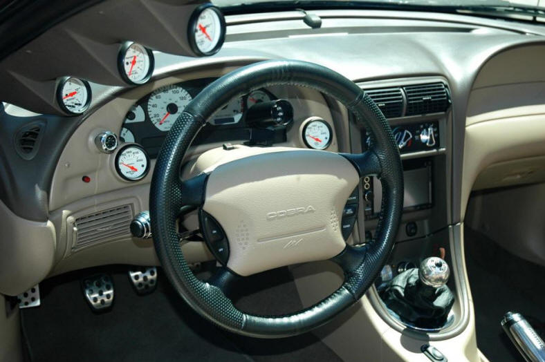
The bottom right photo of the above composite shows the back of the instrument cluster bezel with the two new temperature gauges installed. The photo at the bottom left is a close-up of the oil temp gauge's wiring. The circuits for these two gauges were very simple. Each requires only a single signal wire feed from its sending unit in addition to 12V power and ground connections - plus a variable voltage lighting circuit feed, of course. In the photo below, you can see the way all the gauges looked once this project was complete. I am proud of the way the installation turned out. The additional instruments are so well integrated into the cockpit that I think the casual observer would be hard-pressed to tell this wasn't a dealer-installed - if not factory - option, and that has always been my benchmark for an upgrade well done.
I've created a PDF file containing annotated copies of the photos you see above, which you may find helpful if you decide to undertake a similar project. Just right click the link below and select the Save Target As ... option from the fly-out menu that will appear. 2009 instrumentation upgrade photos (PDF) Here's a more recent shot, this one is from the car's 2011 annual photo shoot.
|