![]()
![]()
![]()
![]()
![]()
![]()
![]()
![]()
![]()
![]()
![]()
![]()
![]()
![]()
![]()
![]()
![]()
![]()
![]()
|
|
|
|
The Solution for IRS Wheel Hop
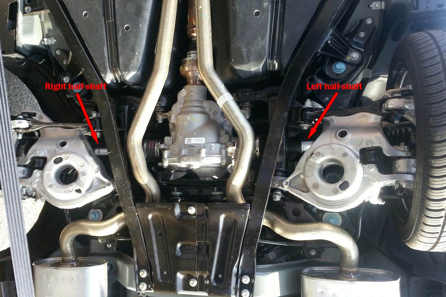
How to best address the wheel hop exhibited by IRS Cobras during hard launches has been a hotly debated topic for years. Since all ’99 – ’04 Cobras demonstrate this idiosyncrasy to a greater or lesser degree, depending on power level and tire/suspension choices, the quest for a silver bullet has been earnest, and entire companies have sprung up around the promise of a cure for this nasty gremlin. To date, the solutions put forth by the SVT Cobra community have fallen more or less short of this objective. Lower rear tire pressures and softer sidewalls have helped, but are not 100% effective, and they compromise handling. Similarly, reducing IRS compliance by replacing various factory rubber bushings with stiffer materials has yielded varying success at the expense of increased noise and ride harshness. However, none of the currently accepted avenues of remediation, either alone or in concert with one another, has provided the sure cure that enthusiasts have been seeking. No one has yet offered a foolproof answer to this problem, or even a partial solution that isn’t accompanied by tangible compromises in other areas, because no one is focusing on the underlying cause of this wheel hop: axle harmonics. In order to minimize production and spare parts inventory costs, Ford graced all IRS Cobras with two identical half-shafts to drive the rear wheels. The same part fits either side. Consequently, both half-shafts share the same harmonic frequency, and herein lies the root cause of the problem. By virtue of their identical harmonic frequencies, the half-shafts alternately wind up and release at the same rates, resulting in self-reinforcing wheel hop. Since the problem is intrinsic to the basic design of the drivetrain, tire choice, inflation pressure, and suspension tuning simply cannot fix it. Not completely. But that doesn’t mean a silver bullet doesn’t exist, and I am about to reveal it to those of you IRS Cobra owners out there in Internet Land who are genuinely interested in putting a stop to your wheel hop. I’d love to take credit for the solution, but the fact of the matter is that it was discovered back in 2008 by General Motors suspension engineers. The Cadillac CTS-V suffered from exactly the same wheel hop issues as the IRS Cobras, and these engineers were tasked by GM with finding a cure. After analyzing the problem, they concluded that the car's identical half-shafts were at the heart of problem and that changing the effective spring rate of one axle shaft in relation to the other would virtually eliminate axle hop by ensuring the oscillation frequency of each side was different. This proved to be the case, and it eliminated the excitation that had been occurring. The GM solution was to make the two axle shafts different diameters, with the left being somewhat larger than the right. It worked, and the CTS-V now exhibits some of the cleanest, smoothest launches around, despite its enormous torque. This same tactic was later applied to the Corvette ZR-1 with equal success and will undoubtedly work for any IRS-equipped RWD vehicle. GM has applied for a patent on the design, but this doesn’t mean you cannot pursue a similar solution with aftermarket parts. Since the available aftermarket axles are constructed differently from their OEM counterparts, their harmonics differ from the those of the Ford parts. Want to cure your wheel hop? REALLY cure it? Substitute a suitable aftermarket replacement for just ONE of your factory half-shafts. That’s all there is to it. Simple. No futzing around with anything else, and no negative impact on other aspects of your car's nature. This solution is offered as a Public Service Announcement. I stand to gain nothing whatsoever from your implementation of this fix. Well, nothing other than the satisfaction of knowing that I helped you avoid squandering your time, effort, and hard-earned shekels on some half-assed solution that may or may not provide an acceptable reduction in your Cobra's wheel hop. 2014 Update: Well, I have no idea how many - if any - Cobra owners have implemented this IRS wheel hop solution since I published it a few years ago, but it appears that the boys in Dearborn, at least, may have read this prescription and taken it to heart.
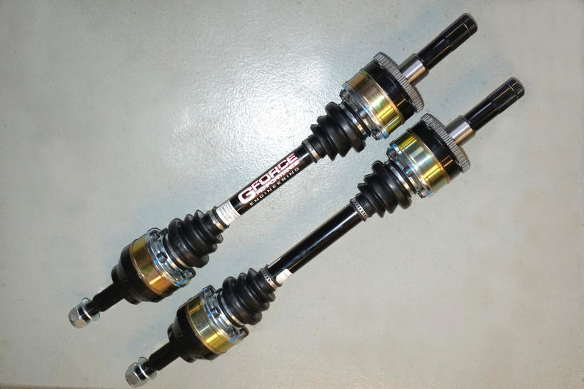
The photo above is a shot of the new S550 rear suspension. The difference in diameters between the left and right half-shafts is readily apparent. Maybe I had something to do with that, maybe not, but I'd like to think I did. (Photo courtesy of my friend Joe, who shot it during a recent trip to Dearborn) 2018 Update: Big news for IRS Cobra owners! An aftermarket axle kit designed to address the New Edge Cobra wheel hop issue has been released. A company named Gforce Performance Engineering, located Wichita, KS, is producing a kit containing 1,000-HP half-shafts of different diameters that are direct bolt-in replacements for all IRS Cobras with 31-spline diffs. Although the diameter difference between the left and right axle bars of the Gforce Cobra Outlaw kit isn't as pronounced as it is in the Ford S550 solution, these half-shafts do appear to solve the wheel hop problem. Taz has been equipped with these half-shafts since December 2017, and I have thus far been unable to provoke any wheel hop, despite having attempted to do so on a number of occasions.
The Gforce half-shafts are fabricated from billet aerospace alloys, are complete end-to-end, and are backed by a lifetime warranty. As a nice little bonus, they will also eliminate any "Cobra clunk" sound that arises from the OEM Terminator tripod CV joints. What's not to love about these things?
Handling Tweaks
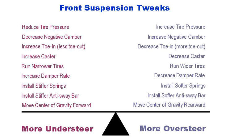
Before tweaking any of your suspension components, you should first address your vehicle's chassis. Don't make the mistake of putting the cart before the horse, so to speak. Chassis stiffness represents the cornerstone of vehicle handling. If you begin your suspension tweaks without having first established a sufficiently rigid platform, many of your tuning efforts will have been in vain if/when you later decide to address the chassis at some point. You will need to revisit all of those prior tweaks if you are seeking optimal performance. Yes, chassis stiffness makes that much difference. In their paper The Effects of Chassis Flexibility on Roll Stiffness of a Winston Cup Race Car (SAE #983051), Thompson, Soni, Raju, and Law observed that increased chassis stiffness alters vehicle handling by allowing the suspension components to control a larger percentage of its kinematics. In other words, chassis rigidity becomes an integral component of every suspension element, and the net effect of any handling tweak will change as chassis stiffness changes. Although you may believe that your car's chassis is already plenty stiff enough, I doubt it. There aren't more than a handful of vehicles on the road that wouldn't benefit from some reinforcement, and yours is very unlikely to be one of them. Tying your car's individual chassis sections together with subframe connectors makes for a nice start, but provides only longitudinal stiffening. You'll also need to increase diagonal rigidity if you want to really improve your car's handling. Increasing your chassis' torsional stiffness is crucial in stabilizing the platform under the kind of loads encountered when braking into and accelerating out of turns. Move on to the handling tweaks listed in the table below only after you've attended to the chassis. Once you've got the chassis sorted out, use the tweaks in this table as guidelines for fine tuning your car to exhibit more or less understeer (push) through turns. As you can see, adjustments to the front suspension invariably have the opposite effect of the same tweaks to the rear. For example, a stiffer anti-sway bar up front will further aggravate an understeer problem, while a stiffer rear bar will reduce it. If you think of the car's handling envelope as a seesaw with its center of gravity as its balance point, the notion of the same modification having the opposite effect at one end than it does at the other makes perfect sense.
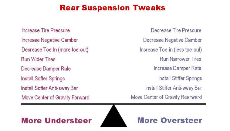
NOTE 1: For the perceptive among us, the above table implies that progressive rate springs aren't the best for handling predictability. As they compress, progressive springs change their rates. While this non-linear performance does help to mitigate bump harshness, it can also result in a car that's a real handful at the limit. NOTE 2: Loads of front caster may be great for high speed stability, but not so much for cornering. Too much front caster increases both understeer and tire wear. Many "experts" disagree on this point, and recommend more caster to reduce understeer. However, the right choice is easy to confirm with a good set of C/C plates. Try going both ways and see which works better for you. I think you'll find my recommendation is correct. Let's now shift our perspective and look at each end of the car independently of the other. For each end, let's put understeer on one side of a balance beam and oversteer on the other, with neutral handling at the beam's balance point and consider what effect various tweaks at that end produce with respect to the vehicle's overall handling.
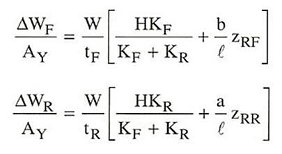
These two graphics help to reinforce the idea that understeer or oversteer can be mitigated by tweaks to just one end of the car. However, as previously noted, the prescribed tweaks at one end will be the opposite of those necessary at the other. NOTE 3: An extremely stiff suspension may be just the ticket for a glass-smooth race track, but not so much for public roads. A suspension that isn't compliant enough will skitter over surface imperfections and undulations, preventing the vehicle's tires from maintaining good contact with the road, and this will compromise handling. Every road car eventually reaches a point at which going stiffer becomes counterproductive. If your car has reached this point, rather than continuing to increase stiffness at one end or the other when tweaking your car's handling, try going softer at the opposite end to alleviate the situation. NOTE 4: Most performance springs are somewhat shorter than the OEM springs they replace. When installing new springs, a conservative approach with respect to vehicle height reduction is generally best from a performance perspective. Up to a point, dropping a vehicle's ride height will improve its handling due to a reduction in its center of gravity. However, extreme lowering adversely affects steering response and roll center (not the same as center of gravity), due to the accompanying changes in suspension geometry. Those interested in a technical presentation of handling optimization are encouraged to obtain a copy of a book titled Race Car Vehicle Dynamics by Bill and Doug Milliken. This book is considered by most to be a seminal work in the field of suspension design, and presents the formula below for calculating a car's lateral weight transfer at each end during cornering.
In the above formula,
W = total vehicle weight (lbs)
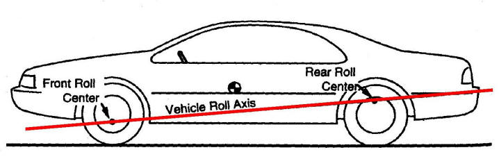
As you can see, a vehicle's front and rear lateral weight transfer depend on different variables, and are quite unlikely to be identical. This is why chassis torsional rigidity is critical for the most predictable handling behavior. Most enthusiasts, and even many automotive professionals, believe that increasing the spring rate and/or anti-sway bar stiffness at one end of the car will decrease the lateral weight transfer at that end due to the enhanced roll stiffness, but exactly the opposite occurs according to these equations. (Plug some realistic test values into the equations to confirm this for yourself.) Weight transfer is increased even though roll angle is decreased. Although most "experts" presume a positive correlation between roll angle and weight transfer, that supposition simply isn't supported by the physical world. Think of a vehicle with NO suspension at all. Recall that little red wagon from your childhood. It had no suspension and, therefore, no roll angle when turning, right? But it most certainly did exhibit lateral weight transfer, as evidenced by the fact that it tipped over when you tried to turn too sharply while going fast. That tip-over was the end result of the wagon's weight being transferred to the wheels at the outside of the turn coupled with a centrifugal force being applied through a lever arm (the vertical distance between the wheel centers and the wagon's center of gravity with you onboard). For vehicles with sprung weight, i.e. those with suspensions, front weight transfer is decreased and rear weight transfer is increased by reducing the vehicle's front roll stiffness (softer springs and/or sway bar) relative to the rear. The opposite effect would be achieved by installing softer springs/bar at the rear. It is this manipulation of the balance between the vehicle's front vs. rear weight transfer (a component of the vehicle's "roll couple distribution") that alters its tendency toward either oversteer or understeer. As you can see in the table above, the prescription for reducing understeer is always to decrease the weight transfer at the front and increase the transfer at the rear. Dampers play a part in the interrelations among the various forces acting on the car by controlling the RATE of lateral weight transfer at each end. In this respect, their contribution is transitory. During the transitional period between initiating a turn and becoming fully established in it, the dampers will affect the vehicle's DYNAMIC roll stiffness at each end. They have no effect once the car has settled into a steady-state turn. Consequently, damper tuning will affect the car's handling behavior, but only while the suspension is transitioning. Of course, every vehicle's basic suspension geometry contributes very significantly to its handling nature. This geometry determines the front and rear roll centers, which is why excessive lowering can be counterproductive when it comes to handling. Each roll center is the point in a transverse vertical plane passing through its pair of wheel centers (front or rear) at which lateral forces can be applied to the sprung mass (body and chassis) without producing an angular displacement (i.e. roll) of this mass. Due to design considerations and differences between the front and rear suspension geometries, a vehicle's front and rear roll centers are almost never the same height, with the rear roll center typically being much higher. Each roll center height is significant with respect to the jacking forces imposed on that end of the car during cornering. The farther a roll center is below the vehicle's center of gravity, the greater the roll angle when side forces are applied, but the less the tendency for jacking. This is because lateral forces on the sprung mass act through a longer lever arm as the roll center moves farther below the vehicle's center of gravity. An imaginary longitudinal line drawn between the vehicle's front and rear roll centers defines its roll axis. (Refer to the sketch below.) A higher overall roll axis results in less linear steering, but quickens chassis responsiveness, while a low roll axis has the opposite effect. As you can appreciate, roll axis position, like most mechanical design features, is a compromise. Too low and we get excessive roll, too high and other undesirable handling traits surface. In practice, the compromise varies with different types of cars but always such that some roll occurs.
The front-to-back angle of the roll axis above the horizontal plane is called the roll axis inclination. Generally, a vehicle's yaw damping improves as its roll axis inclination is increased (becomes higher at the rear). Also, to mitigate body roll, the roll axis should pass reasonably close to the vehicle's center of gravity. During transient maneuvers, such as entering/exiting turns, a myriad of transitory force vectors affect the vehicle's handling. The static roll centers move around and become instant centers, etc. Consequently, accounting for dynamic loading and vehicle transient behavior can become very complex, requiring tools such as Finite Element Modeling (FEM). A technical presentation of these esoteric analytical methods is beyond the scope of this discussion. Those interested in delving into the nether regions of suspension design are encouraged to consult the Milliken text noted above and other advanced references. However, this presentation should suffice for anyone primarily interested in fine tuning the handling of his/her own vehicle.
Calculators
NOTE: The calculator links below will display Microsoft Excel workbooks. You must have Excel installed on your computer to view and use these calculators. Forced Induction Calculators (Excel) Fuel Injector Calculators (Excel) Tire & Drivetrain Calculators (Excel)
TECH TIP: Projecting your power increase per pound of boost is perfectly straightforward. I don't understand why people insist on making something mystical out of the process. Atmospheric pressure at sea level is 14.7 psi, so this would be the theoretical intake air pressure at WOT for a naturally aspirated engine at sea level. Adding one psi of boost increases the intake air density by a approximately 6.8%, or 100 x (1 psi / 14.7 psi), so the the percentage increase of intake air pressure resulting from 'D' psi of boost, where D is a target boost level, is as follows: Percent intake air density increase = 100 x (D / 14.7) For example, if we observe 9 psi of boost pressure in the intake manifold, the intake air pressure has been increased by the following: Intake air density increase = 100 x (9 / 14.7), or 61.22% Now, given a corresponding increase in fuel delivery to maintain the A/F ratio, we can expect to make a theoretical maximum of 61.22% more power, minus pumping losses and parasitic drag. Most twin-screw setups are about 78% efficient, so our expected net power increase becomes 0.78 x 61.22%, or 47.8%. For example, if we were making 300 RWHP N/A, we could expect to make somewhere around the following power after introducing 9 psi of twin-screwed boost: Estimated pwr @ 9 psi = 300 + (0.78 x 300 x 9 / 14.7) = 300 + 143.27 = 443.27 RWHP Granted, this power increase is purely theoretical, and various factors can introduce reductions to the calculated value. But it's almost exactly the power increase that many, including myself, have observed, so it's a fairly reliable rule-of-thumb calculation. Please note that the same 6.8% gain per psi does NOT apply when adjusting boost from one level to another, for example when increasing your boost level from 9 psi to 12 psi. The 6.8% constant is derived from ATMOSPHERIC PRESSURE at sea level, so the engine's naturally aspirated power must always be used as the baseline when calculating projected power increases. Always work off that baseline.
General Info, Maintenance, & Repair
This section contains a collection of technical references that include my own compositions, reference documents compiled from multiple available resources, and external references reproduced in their entirety. NOTE: All links below will take you to Adobe Acrobat (PDF) files. If you haven't already installed Adobe Acrobat Reader on your computer, you can download it free from the Adobe Website. Cooling System Electrolysis Testing Differential Installation & Repair Dropping the K-member to Replace the Motor Mounts Emissions Equipment Diagnosis and Repair Engine Piston & Ring Evolution Ford Motor Company OBDII Diagnostic Code Cross-reference Table Fuel System Requirements Based on BSFC Manual Transmission Diagnostics Misfire Diagnosis and Correction Preventive Maintenance Schedule for OCD Personalities Ring & Pinion Tooth Pattern Interpretation Rotor Crossdrilling Effects on Braking Performance Steering Rack R&R on a New Edge Mustang Supercharging - General Information Supercharging vs. Turbocharging Comparison Tune-up Procedures and Maintenance Items Twin-screw Supercharger Operating Principles
Project Notes, Diagrams, & Photos
NOTE: Some of the files linked below are quite large, because they contain numerous photos. You should download any/all that you are interested in viewing to your own computer. To download one of these files, right-click on its link and select the "Save Target As ..." option from the fly-out menu that will appear. These files, like the General Maintenance & Repair files above, are all Adobe Acrobat (PDF) files. You will need to have Adobe Acrobat Reader installed on your computer in order to view and print them. 2002 Suspension Upgrades Installation Notes 2004 Instrumentation Upgrade Installation Notes 2006 Mach 460 Audio System Modification Photos 2006 - 2007 Driveline & Suspension Upgrade Installation Photos 2009 Instrumentation Upgrade Installation Photos 2011 Nav-Media Project Annotated Photos & Wiring Diagrams (LARGE) 2013 Courtesy Lighting Project Wiring Diagram HID Headlamp Project Installation Photos Ported Intake Installation Notes
External References
NOTE: Selecting any of the links below will open the external reference in a new browser window. Automotive Suspensions - technical description - Wikipedia Disc Brakes - technical description - Wikipedia Double-Clutching - technical description - Wikipedia Exhaust Gas Recirculation - technical description - Wikipedia Heel & Toe Shifting - technical description - Wikipedia Manual Transmission - technical description - Wikipedia Positive Crankcase Ventilation - technical description - Wikipedia Rotational Inertia - technical description - Wikipedia Supercharger - technical description - Wikipedia Turbocharger - technical description - Wikipedia Unsprung Weight - technical description - Wikipedia
|