![]()
![]()
![]()
![]()
![]()
![]()
![]()
![]()
![]()
![]()
![]()
![]()
![]()
![]()
![]()
![]()
![]()
![]()
![]()
|
|
|
|
Billet Rack Bushings
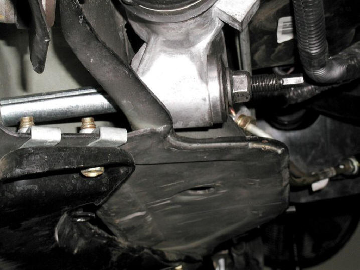
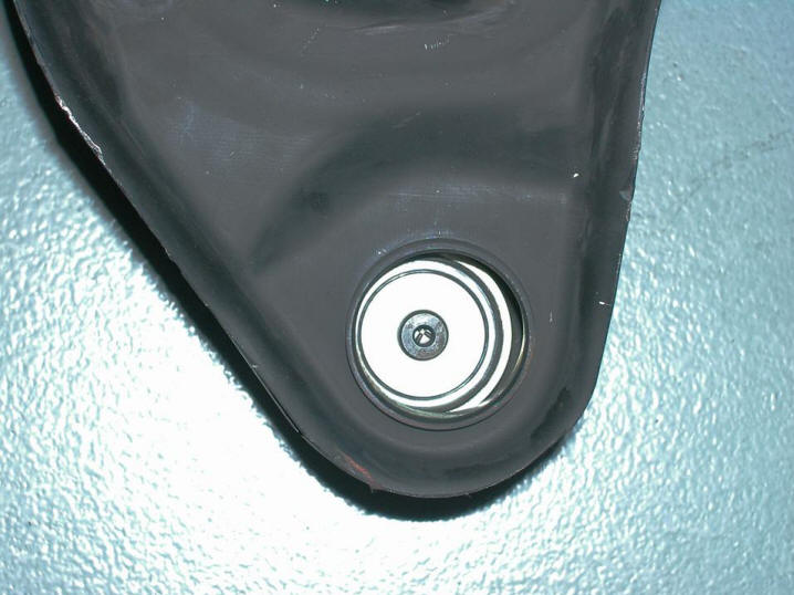
I decided in 2002 to perform a minor steering system upgrade while I had the car in the air for its initial suspension work. The factory rubber steering rack bushings contributed somewhat to the car's lackadaisical steering response, but Maximum Motorsports offered billet aluminum replacements to eliminate this hysteresis. I bought a set, even though I was afraid that I might be introducing too much harshness and steering wheel kickback with the aluminum rack bushings, because I figured I could always switch to poly if the aluminum bushings proved too brutal. But my fears were unfounded. The power steering system did an admiral job of dampening any increased kickback, and although NVH over rough pavement did rise a bit, turn-in response improved substantially. I considered this an acceptable tradeoff, and the bushings have been on the car ever since their installation. The swap was very straightforward and took practically no time at all, with marking and cutting the sheet metal bolt sleeves taking more time than anything else. The photo below shows the passenger side steering rack bushing after installation:
TECH TIP: The key to performing this upgrade quickly and easily is to make use of the fact that each rack bushing is composed of two separate rubber pieces forming a front and back half to the bushing. There is a small void between them inside the rack eye. If you encounter any difficulty in removing your bushings from the rack eyes, place a couple wooden spacers between the rack and the K-member near the bushing locations. Then, insert a small flat blade screwdriver through the front half of each bushing and into the void between it and the back half. Angle the screwdriver so that its tip presses into the inside face of the back bushing half, and knock the back half out the back of the rack eye by tapping the screwdriver with a rubber mallet. Once the back halves of the bushings are out, move around to the back side of the rack and knock out the front bushing halves from behind. Quick and simple. NOTE: The car's aluminum rack bushings had been in place for some time when Max Motorsports released a spherical bushing upgrade kit for them. I purchased the kit and installed it along with Taz's other 2006 - 2007 upgrades. The upgrade kit is included with MM's newer bushing kits, so don't worry about buying the upgrade separately unless you already own one of the older bushing sets.
Steering Shaft
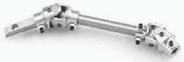
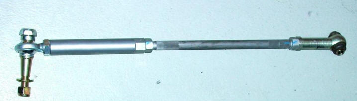
The heat radiating off my driver side JBA header eventually destroyed a rubber grommet on the OEM steering shaft, resulting in considerable play in the steering and an annoying clanking sound whenever I sawed the wheel. Since the stock shaft had been constructed with a rubber rag joint that tied it to the rack, it had always felt somewhat spongy and vague, anyway, so I decided to replace the entire assembly with one manufactured by Borgeson Universal. I shot no photos of the Borgeson part before installing it, but it looks much like the steering shaft depicted below.
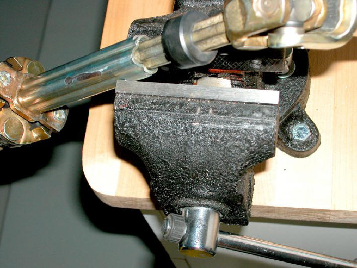
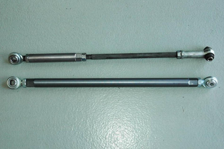
The Borgeson intermediate shaft is a precision piece that provides a second U-joint in place of the stocker's rag joint. Furthermore, unlike the stock part, the Borgeson does not employ a rubber grommet to secure an ill-fitting inner shaft to an oversized outer tube. The photo below of the stock shaft after its removal clearly shows the size of the gap between the inner and outer shaft pieces. A ridge on the underside of the grommet that has been moved up the inner shaft for a better view is normally press-fit into that gap. However, exhaust heat causes the grommet to become brittle and the ridge to disintegrate, leaving metal-to-metal contact that results in a dead zone and disconcerting delay in steering response, as well as the annoying clanking sound mentioned above.
Although I wasn't aware of it until I removed the stock intermediate shaft from the car, it had been rubbing on my driver side JBA's collector tube ever since the header installation. You can see the wear pattern on the OEM shaft's outer tube in the photo above. Together, the intermediate shaft and steering rack bushing upgrades worked wonders to firm up the Cobra's steering response and improve feedback, but it wasn't until I performed the 2006 suspension upgrades, which included front and rear bumpsteer kits and new front control arms with revised geometry, that the car finally exhibited handling precision more in line with I had envisioned all along. Refer to the Chassis & Suspension page of this site for a description of additional modifications related to improving Taz's corner carving capabilities.
X2 Balljoints & Front Bumpsteer Kit
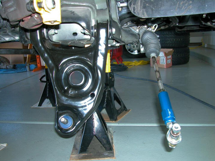
Lowering a car with performance springs alters its steering geometry and lowers its roll center. In the worst case, the roll center actually drops below ground level and moves from side to side as the body rolls. This results in lost grip and erratic handling, and the lower roll center also increases body roll. To correct these problems and restore the front roll center geometry, Steeda offers a specially designed balljoint kit. The X2 balljoint kit accomplishes its mission by raising the front spindles relative to the balljoint pivot points. This provides reduced body roll, quicker steering response and improved overall front tire grip. I installed the X2 balljoints while performing Taz's 2006-2007 driveline and suspension upgrades, and they've been on the car ever since. TECH TIP: Unlike the OEM balljoints, which are sealed, the X2's are equipped with zerk fittings. The X2's should be lubed semi-annually, at the very least, to maintain their performance. I use either Red Line CV2 or Mobil 1 Synthetic Grease in mine, and I lube them every time I change the car's engine oil. Another foible that requires some attention when lowering a vehicle is bump steer. Although automotive engineers strive to minimize both bump steer and roll steer, which are related, most suspensions exhibit some of each, and altering the ride height of a car generally increases their levels. As many already know, both bump steer and roll steer arise from unwanted toe changes as the vehicle's suspension travels through jounce and rebound. The difference between the two is that bump steer occurs as both wheels at one end of a vehicle travel up and down together, while roll steer occurs when one wheel rises as the other falls, generally resulting in more toe-in on one wheel and more toe-out on the other, producing a directional steering effect. What's the best way of addressing these two issues concurrently? Sway bar changes will alter roll steer, but not bump steer, so that's not the solution. We need to minimize the amount of toe change at each wheel as it moves through its operating range. In order to do that, we must first understand the underlying cause, the mechanism behind these steering gremlins. Think back to your days of snoozing in geometry class. Does the formula A2 + B2 = C2 sound vaguely familiar? I hope so. It's relevant here. In this situation, the tie rod itself will be line C (the hypotenuse of our triangle). Now, visualize an imaginary line extending from the tie rod's inner attachment point to its outer tip but parallel to the ground. Let's call that line A. Finally, line B will be the vertical drop from the tie rod's outer end to the end point of imaginary line A. Got a good visual of this imaginary triangle? If not, sketch it. Go ahead; I'll wait. Now, let's increase B by reducing the vehicle's ride height, which will increase the angle formed by the intersection of A and C. Note that this results in a tie rod that is now effectively too short. And, because the tie rod is now too short, it can no longer reliably follow the vehicle's suspension movements. See the way that works? In an extreme case, this restricted movement of the steering arm results in immediate, nasty toe changes whenever the suspension is jounced. Furthermore, suspension travel is continually attempting to pull the tie rods out of the rack to make them long enough, tearing the rack seals in the process. Ever wonder why the steering rack on your lowered car has begun to leak? Mystery solved. A good bumpsteer kit is imperative for correcting and optimizing steering behavior, especially on a vehicle that has undergone ride height alterations. Fortunately, excellent kits are available from a number of vendors. These kits enable optimization of the tie rod's angle by allowing its pin height to be adjusted for maximum range of rod movement. I picked up a Steeda bumpsteer kit along with my X2 balljoints, and installed it at the same time. In the photo below, you can see an X2 balljoint installed on a new right front control arm and an adjustable tie rod end from the bumpsteer kit installed on the tie rod.
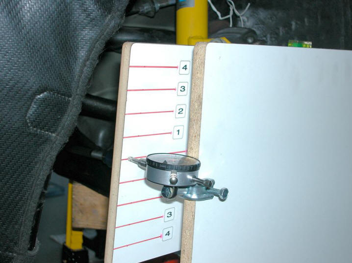
Obviously, installing a bumpsteer kit does little good without some way of making informed adjustments. Toward that end, I picked up a Maximum Motorsports MMT-4 bumpsteer gauge to help me correctly adjust mine. The photo below shows the gauge being used to bumpsteer the left front.
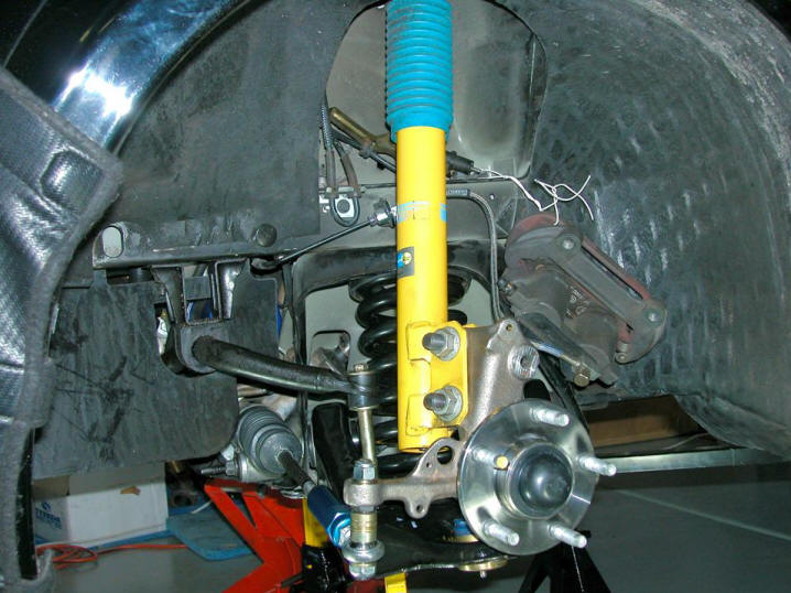
Here's a shot of the left front after I had completed the bump steer adjustments.
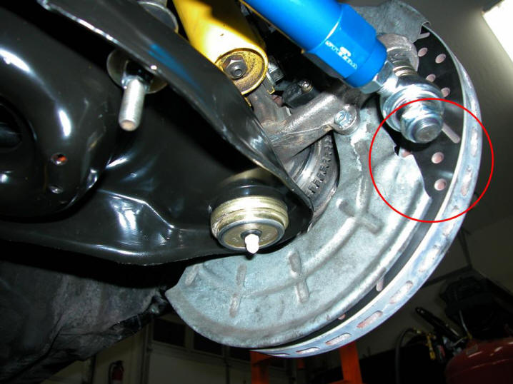
Steeda recommends removing the front brake shields from the car after installing X2 balljoints. But I wanted to retain the insulation benefits that the shields provided, so I mounted one on the car during its bump steer adjustments. That way, I could determine exactly where I had interference issues and what I needed to do about them. I found two areas of the shield where I could avoid potential binding by slightly tweaking the sheet metal away from the hub and knuckle, and one spot where my best option was to remove a small section of the shield. The area circled in red below indicates where I sliced off a portion of the shield with a Dremel cutoff wheel. Problem solved.
Ford Racing Front Control Arms
I installed Ford Racing Terminator front control arms (shown in the section above) along with the Steeda X2 balljoints and bumpsteer kit. Compared to the OEM '01 control arms they replaced, the Ford Racing control arms incorporate revised geometry and 50% stiffer bushings. The stiffer bushings reduce the elasticity in the car's steering, while overall handling is improved by moving the balljoint locations forward by about a quarter inch. This extends the car's wheelbase, improving its Ackermann steering geometry and shifting its center of gravity a tiny bit rearward for slightly better F/R weight balance. The photo below is a shot I took of an OEM 2001 Cobra front control arm from which I have removed the balljoint lying directly atop its Ford Racing replacement in order to demonstrate the difference in balljoint locations. The offset of the balljoint in the Ford Racing control arm compared to the balljoint mounting location in the OEM arm clearly illustrates this difference. In this photo, the undersides of both arms are facing the camera and their leading edges are toward the left.
My motivation for installing the Ford Racing FCA's was twofold. First and foremost, I wanted to capitalize on the handling benefits offered by their revised geometry. Second, I was attracted by the sharpened responsiveness to steering input that their stiffer bushings promised. I had initially considered fitting urethane bushings to the factory arms, but they wouldn't have provided the improved geometry. Besides, I had received reports of objectionable harshness from friends who had tried poly bushings in their front control arms. Granted, those friends had opted for very high durometer bushings, and I have since had two other friends, who installed softer Energy Suspension bushings in their FCA's, tell me that they didn't experience a significant increase in NVH following their installations. Nevertheless, I'm still glad I decided to install the complete Ford Racing arms. Their improved geometry has provided a tangible handling benefit, and their stiffer-than-stock rubber bushings have tightened up Taz's steering quite nicely. If and when the rubber in these FCA's must be replaced, I'll try the Energy Suspension bushings in them. Until then, or at least until I've driven a car equipped with them, I cannot personally endorse any urethane FCA bushings as a suitable solution for a street-driven car because I've had no firsthand experience with them.
Rear Bumpsteer Kit
An IRS-equipped Cobra is susceptible to developing bump steer and roll steer issues not just up front, but out back, as well. To counteract these unwanted rear suspension steering inputs, I installed a Maximum Motorsports rear bumpsteer kit at the same time as the Steeda front bumpsteer kit. The photo below shows a Max Motorsports adjustable tie rod end installed on the left rear tie rod.
After installing the rear bumpsteer kit, I used the same Maximum Motorsports bumpsteer gauge that I had used up front to make the correct adjustments out back.
Max Motorsports Trailing Links
One of my periodic maintenance procedures involves to re-torquing the Cobra's rear axle nuts and checking for play. In early 2011, this procedure revealed a bit of L/R slop developing in one of the wheel/tire assemblies, despite the axle nut still registering the specified torque value. A quick investigation revealed that the play was originating at the trailing link's inner attachment point. Its OEM rubber inner bushing was beat. Fortunately, those of us who had already purchased the Maximum Motorsports IRS bumpsteer kit (see above) could upgrade to the MMIRSTR-3 full length competition trailing link replacement kit for a very reasonable price. These links replace the rubber inner bushings with Heim joints, as well as providing much more rigid construction. One of the new links is pictured below one of the takeoff parts in the photo below.
Installation took only a few minutes. In fact, adjusting the lengths of the new parts to match those of the takeoffs took as long as the removal and replacement process. More importantly, this upgrade has eliminated the toe slop that had begun to manifest itself.
|