![]()
![]()
![]()
![]()
![]()
![]()
![]()
![]()
![]()
![]()
![]()
![]()
![]()
![]()
![]()
![]()
![]()
![]()
![]()
|
|
|
|
OEM Audio System Modifications
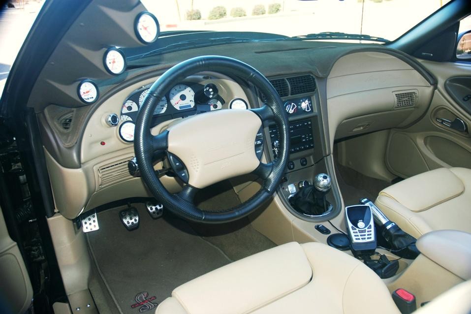
While I was still running the stock Ford Mach-460 audio system, I performed a couple minor upgrades designed to enhance my listening pleasure. I had discovered that the double-DIN head unit possesses not only a built-in multi-disc CD player, but also the signal and control circuitry required to accommodate a second, external disc changer or other auxiliary audio source, such as an MP3 player, a satellite receiver, etc, and I decided to put that capability to use. Another standard feature built into each Mach 460 is speed-sensitive volume (SSV) circuitry, but this SSV capability remains dormant in the Mustang incarnation of the system. (I suppose some bean counter figured he'd save Ford a nickel on each car by eliminating the single wire and connector necessary to tie the SSV circuit into the signal from the vehicle's speed sensor.) For years, I did nothing about hooking up the head unit's SSV circuit, because I just didn't listen to the audio system often enough to warrant the effort. About the only times I enjoyed hearing some tunes in the car were during long road trips, and in that setting, I could adjust the volume for highway cruising and forget about it. Around town, the audio system usually remained off, because I preferred listening to the Cobra's mechanical song. Sadly, listenable FM stations were/are few and far between on the highway, so I began toying with the notion of adding a satellite radio receiver to the car and feeding the signal to the OEM audio system via its auxiliary input. In mid-2005, I purchased a small JVC SIRIUS satellite radio receiver, complete with matching mobile, home, and portable kits, but I postponed tying it into the car's Mach-460 for several months. The 2001 through 2003 audio head units are equipped with "Worldplug" 3-receptacle connector systems. (2004 head units do not use the same style connectors.) Although I had been reading for some time about a product from a company named Precision Interface Electronics that claimed to make connecting any external audio source to a Mach 460 head unit a clean and simple procedure, some controversy had arisen among New Edge Mustang owners about whether or not the "PIE adapters," as they were called, really did work as advertised in our cars, and I wanted confirmation before proceeding. Finally, by January 2006, enough people had reported positive results with their PIE adapters for me to feel reasonably confident about making one work in Taz. I ordered mine directly from the manufacturer, and it arrived at my doorstep just a few days later. Since I needed to pull the head unit out of the dash to install the PIE adapter anyway, I decided to also connect the unit's SSV circuit to the vehicle speed sensor at the same time. I am pleased to report that I managed to accomplish both objectives with relatively little drama. Afterward, Taz's audio system boasted speed-sensitive volume and was able to play audio from my SIRIUS receiver or any other external audio source, such as my MP3 player. With regard to mounting the little JVC receiver, I was delighted to discover that the car kit's windshield mount slipped nicely down into one of the console cup holders once the rubber boot had been removed from the recess. Since the mount was nicely articulated at both ends, I was able to easily reorient the receiver any way I liked. Using this mounting location also made it easy to obtain the requisite 12V power for the receiver from the auxiliary power port inside the console's storage compartment. I was able to store most of the extra wire inside the console, as well, so the interior still looked reasonably neat with the receiver sitting in the console. This is the way everything looked with the JVC hooked up:
2009 Update: In 2009, I rerouted the auxiliary audio signal cable (visible above) through the console, so it emerged between the emergency brake handle and the rear cup holder for a much cleaner appearance. For those of you who are interested in making similar modifications to your own Mach-460's, I shot a few photos while performing these upgrades, and I threw them into a PDF with a simple circuit diagram detailing the connections. Sorry about the quality of the photos, my former digital camera had become possessed. (Even though the problem was most likely pilot error, I subsequently replaced that camera with a better one.) Anyway, here's a link to the file: Mach-460 modification wiring diagram & photos (PDF) NOTE: A shroud of mystery, folklore, and just plain fantasy has surrounded the factory Mach 460 audio system ever since it debuted. I have researched the system as thoroughly as realistically possible, tapping all the resources I could turn up, so allow me to shed some light on the topic. These tidbits of trivia represent the end result of countless hours of sifting through mountains of misinformation, many completely bogus allegations, and much pure conjecture to uncover the truth. This is what I discovered: First, 99.999% of the "information" about this system that is floating around out there on the Internet is sheer NONSENSE! (Gee, imagine that. Bad information in Cyberspace. How unusual.) Most threads on the topic are populated primarily by posts containing nothing more than pure conjecture and questionable opinion in lieu of any objective information, all typically delivered with the borderline illiteracy that is far too prevalent in our culture these days, and nearly all are littered with bad data. If the bullshitters and axe-grinders would have just kept their ignorance to themselves, instead of inflicting it on the rest of us, the amount of information I had to wade through to uncover anything genuinely helpful would have been reduced by 99.998%. So, what's new, right? Second, the 460-watt claim for the factory system is not a true continuous power rating. Not even close. We're talking typical mobile audio specs here, which hail from the world where the Good Ship Lollipop sails. Unlike the manufacturers of professional sound reinforcement gear and high-quality home equipment, car audio companies have employed various deplorable tactics to artificially pump up their power output numbers. The motivation, of course, is to make their junk more alluring to the pimple-faced rubes generally found shopping for car audio gear. Hence, we see power rating schemes such as "Dynamic Peak Power," "Total Music Power," "Maximum Power," and other fantasy yardsticks being bantered about. Frankly, I'm amazed that no one has yet adopted the "ILS" (In a Lightning Storm) power measurement scheme. Regardless, all those puffed up ratings are meaningless. The only power rating that truly matters is an amplifier's CONTINUOUS sine wave output at its rated distortion and across its specified power bandwidth, i.e. its standard RMS power. Unfortunately, despite my best efforts, I was never able to uncover specific RMS power figures for the Mach 460's amplifiers, so I'm forced to stick with the silly "Maximum Power" numbers. However, unlike so many others, I'll break them down correctly for you. The 4-channel midrange/tweeter amplifier (internal to the head unit in an '01 or newer vehicle, or housed in a separate case below the head unit in an earlier car) is capable of 120 watts of combined peak power. That's 30 watts of peak power for each of the system's four midrange/tweeter transducers. (RMS power would likely be somewhat less than half of this figure, most likely somewhere between 10 and 12 watts per channel.) The remaining 340 watts of the rather optimistic 460 are delivered to the four midrange/woofer drivers by a pair of monaural amps mounted behind the rear seats. That works out to 85 "ILS" (couldn't resist) watts of power per speaker. Between them, these two amps deliver the same exact signal to all four mid/woofer speakers, so there's no left/right or front/back trim control provided for them by the OEM head unit. If you have a factory Mach audio system, you may have noticed that the mid/bass speakers are unaffected by balance or fade adjustments. Only volume and tone control adjustments alter their audio output in any way. Third, as should be already apparent, each of the Mach 460's speakers delivers only a portion of the entire musical spectrum. The Mach head unit contains internal high and low bandpass circuitry to divvy up the frequencies prior to sending them out to the amps and, subsequently, to the speakers. HOWEVER, the allocation of frequencies is unconventional, which is why aftermarket component tweeters that don't include high-pass filter capacitors generally enjoy life spans akin to fruit flies when installed as replacements for the factory midrange/tweeter transducers in vehicles still using the OEM electronics. I have read conjecture, speculation, and WAG's (Wild Ass Guesses) placing the crossover point between the Mach's mid/tweeters and mid/woofers at anywhere from a low of about 100 Hz to a high of 2500, with a fairly even distribution of guesses in between those two extremes. During all of my research, I read only one allegation in which I placed any stock at all. This was posted by an individual who claimed to have worked on the Mach 460 project for Visteon, the system's manufacturer. That person pegged the crossover point at 300 Hz, which sounds plausible to me. A crossover frequency very much higher would smear the system's imaging (instrument placement within the soundstage) because of the various speaker locations, and a lower crossover frequency would severely jeopardize the fragile voice coils of the small mid/tweeter speakers, not to mention the fact that asking those little cones to reproduce sounds as low as even 300 Hz is really asking quite a lot from them. Fourth, the midrange/bass amps are continually supplied with 12V power, but are switched on and off remotely from the Mach 460 head unit by "trigger" wires. Each mid/bass amp is remotely controlled by its own trigger wire, so if you're getting bass out of only your door speakers or only the rear speakers, check the related amp's trigger connection before anything else. The amp located on the driver side of the car powers the mid/bass speakers in the vehicle's doors, while the passenger side amp controls the pair in back. Each amp is equipped with two wiring harness receptacles. The trigger wire is the one connected to pin #2 on the connector containing that amp's speaker leads. (I can't speak for a coupe, but in a ragtop, this is the connector on the side of the amp facing the trunk.) In my car, the trigger wires' jacket colors are GRN/VIO at the driver side amp and GRY/BLK at the passenger side amp. 2011 Update: These OEM audio system modifications were superseded by replacement of the Mach 460 head unit with a JVC in-dash navigation/media system. Refer to the section below for details about that project.
2011 Media Equipment Upgrades
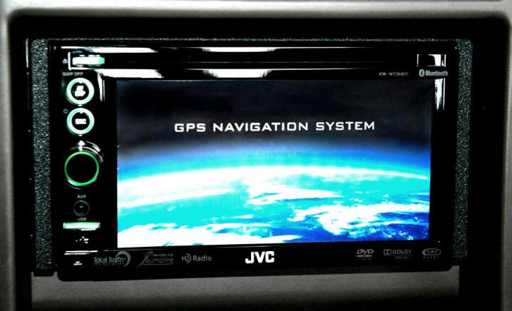
For Christmas 2010, Santa Hillie (wifie) gifted me with some swell navigation and entertainment gear for the Cobra, specifically a spiffy new JVC KW-NT3HDT double-DIN in-dash unit and the ancillary modules required to add satellite radio reception. This fleshed out the front end of Taz's entertainment system very nicely and effectively ended a moratorium I had declared on the car's upgrade program over a year earlier. Of course, true to my "off the chain" nature, I added to the complexity of this project by throwing additional hardware into the mix. To wit, I persuaded myself that it would be a shame to install such an outstanding new head unit and not take full advantage of its sophisticated bandpass circuitry by adding a few low bass components. During the years subsequent to my buying the Cobra, I really hadn't logged sufficient listening hours to justify investing the time, effort, or moola necessary to pump up Taz's audio system beyond simply adding satellite radio reception. After all, the factory Mach 460 certainly sounded good enough to support the infrequent use it received. However, the new JVC unit with which Hillie had gifted me promised significant enhancements to Taz's media capabilities, as well as the addition of onboard GPS navigation and Bluetooth phone connectivity.
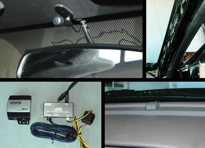
The new head unit certainly expanded my listening options quite nicely, including, among others, SD, USB, Bluetooth, and DVD playback. As a bonus, the unit is equipped with not one, but two HD radio tuners, one for the commercial music/talk channels and one dedicated to the news and traffic update services. It has single-handedly catapulted Taz's media system from the 90's into the 21st century, so you thank very much, Santa Hillie. Naturally, enhanced capabilities are nearly always accompanied by additional installation issues, and this new head unit is no exception, unfurling its tentacles into numerous vehicle circuits and adding new circuitry of its own. A microphone (upper left pane of the composite photo below) had been included with the unit to support its Bluetooth cell phone connectivity, and after some deliberation, I concluded that the center of the windshield header, just above the interior rear view mirror, offered an excellent spot for the mic. Located there, it can be swiveled and tilted on its ball-and-socket base for use by either the driver or passenger. In the upper right panel, you can see the microphone's cable running along the factory harness that travels down the passenger side A-pillar. (This is completely concealed once the trim panel is back in place.)
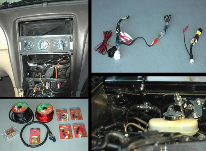
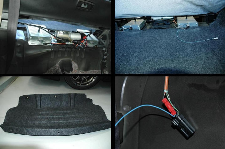
A GPS satellite antenna also accompanied the head unit for use by its navigation circuitry. As you can see in the photo at the bottom right of the above composite, I painted this part to match the dash color and mounted it near the base of the windshield, above the dashboard's center stack. I also painted a second antenna (not shown), which had been provided with the SIRIUS Connect SCC1 tuner, and mounted it on the dash, next to the driver side A-pillar. In the bottom left pane of the above composite, you can see the SIRIUS tuner and the JVC KS-SRA100 satellite radio interface module that Santa had supplied along with the new head unit. I installed both of these modules inside the center stack, below the main unit, where there was ample room for both plus all their cabling. The top left panel of the next composite shows the double-DIN opening in car's center stack after removal of the OEM head unit. At the upper right, is a shot of the JVC's two main wiring harnesses after I had prepared them for connection to Taz's electrical system. The composite's bottom left panel contains a photo of the 4-gauge wire and related parts that I added to the project, not for the JVC unit, but to support the other peripherals that had infiltrated the project (more about those later). In the panel at the bottom right, you can see the new 60-Amp inline AGU fuse holder installed on the Cobra's left inner fender to supply the 4-gauge primary wire.
To facilitate installation, I scored a Metra #70-5519 harness adapter kit, which enabled me to retain the Cobra's OEM plugs when connecting my new head unit into the vehicle's existing audio wiring. The left wiring harness in the panel at the upper right above was created by mating the Metra kit's two adapter harnesses with the main JVC harness and a couple of RCA Y-adapters. The RCA cables would feed the Mach 460's mid/bass amps from the JVC's line level outputs. I added the red and black wires visible at the left of the harness to carry switched power and ground to the JVC KS-SRA100 interface module, and I eventually connected those to the yellow and black wires in the photo of the module depicted in the first composite. This harness also contains the modular high and low bandpass filters that I added to ensure both good audio performance and a margin of safety when running the aftermarket head unit with the OEM speakers. Rather than waxing technical just yet, I'll simply say that it would have been a BAD thing to overlook the addition of those filters, sort of like crossing the streams in Ghostbusters. The factory head unit had incorporated internal filtering circuitry to split the frequencies assigned to the two different speaker types, and even though the JVC was also equipped with internal bandpass filters, these had been designed specifically for use with component subwoofers and couldn't be tuned to frequencies suitable for use with the Mach 460's speakers. Hence, the addition of the modular filters visible in the photo. The harness on the right in that same picture is the JVC's secondary, A/V input harness. I didn't plan on using the audio/video connectors on that one any time soon, but I still needed to install it in order to provide the new unit with signals from the vehicle for reverse and road speed. For the speed signal, I was able to reuse the same VSS wire I had previously pulled for use by the OEM unit. For the reverse signal, I tapped into the 12V backup light wire at the GEM (pin #20 of C352). The top photos in the composite below are shots of my ragtop's factory Mach 460 mid/bass amps, from both the passenger cabin (left photo) and from the trunk. Note that there are connectors located on the opposite ends of each amp. The light blue wire shown in the photo at the upper right is a remote trigger wire that I spliced into the wiring for the Mach amp on the passenger side using a Posi-Lock connector. The photo directly below that one is close-up of the splice prior to dressing it. (As I've mentioned elsewhere on this website, these connectors are worth their weight in gold, as they cannot pull loose the way crimp connectors will.) The photo at the bottom left of the composite shows the plastic partition that forms the forward bulkhead of the car's trunk after I had added a couple grommets to accommodate the cables that I would be pulling through to the trunk. More about those cables in a moment.
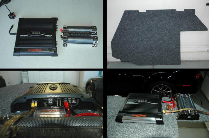
The OEM speakers did an adequate job of reproducing the audio spectrum from the mid-bass up through the high frequencies, but deep bass production, which is dependent to a large extent on speaker surface area, left much to be desired, particularly in a ragtop like Taz. And since my new head unit was equipped with provisions for supporting a sub, I decided to augment the factory speakers in order to tie down the system's bottom end, sonically speaking. TECH TIP: As those who are familiar with the physics of sound propagation are aware, sound production is logarithmic by nature. One decibel (1 dB) is the smallest difference in sound volume that most people are able to discern, but increasing the volume by only 3 dB (making it just "slightly" louder, subjectively speaking) requires twice the amplifier power. There's more. Let's say you're listening to a 1 KHz tone through your speakers. Doubling its perceived volume would require increasing the SPL (Sound Pressure Level) by about 10 dB, but because audio reproduction is a logarithmic function, you'll need roughly TEN TIMES the power to achieve that 10 dB increase. Furthermore, every subsequent doubling of the volume will require another 10 times more power than the previous level. Fortunately, listening at a reasonably conservative volume usually requires only a watt or so, but you should be aware that power demands increase rapidly when pumping up the volume. But wait, there's still more. Our hearing is extremely nonlinear with respect to its sensitivity to different frequencies. We are much more sensitive to sounds around 1 KHz than to low bass notes, so reproducing low frequency notes at the same perceived volume as midrange sounds requires a great deal more power than reproducing those midrange sounds. Although each frequency decade contains 10 times as many frequencies as the one below it, each individual frequency requires only 1/10th the power to reach the same perceived loudness as its counterpart in the next lower decade. That's why pink noise, which contains equal energy per octave, is used for audio system sound calibration and equalization, rather than white noise, which is equal energy per frequency. This phenomenon dictates that an audio amplifier designed for low bass reproduction needs to be capable of BIG power, while the power requirements of amps delivering only midrange or high frequencies fall off rapidly as we travel upward through the audio spectrum. It is also why a very small speaker, such as a tweeter, will burn out quickly when asked to reproduce bass frequencies - the gauge of the wire used in its voice coil is far too small to carry the current necessary to produce low bass notes at any appreciable volume, so the tweeter acts like an expensive fuse when you turn up the volume. This leads us to a related consideration. Because of its hefty power requirements, a low bass amplifier should be as efficient as possible in order to avoid unnecessarily overtaxing a vehicle's battery and charging system. Class-A amps, long prized by audiophiles for their sonic purity, are only about 30% efficient. Most of the power they consume is dissipated as heat, making them impractical for use as automotive bass amps, or any other bass amps for that matter. The more common Class-AB designs are more than twice as efficient, and most automotive amps are Class-AB devices. However, the newer Class-D switching amps, which are typically more than 90% efficient, are now available for use in automotive applications and will eventually replace the AB units because of their reduced demand on vehicle electrical systems. Nonetheless, any bass amp, even a Class-D, can impose enormous instantaneous demands on a vehicle's battery and alternator when you're playing music loud. This is why we see the headlights of many vehicles equipped with large bass amps dimming when loud, bass-heavy tunes are played at night. The power demand of the loud bass depletes the electrical system's reserves and the voltage of the vehicle's electrical system drops, dimming the lights. To avoid this, folks in the know generally add "stiffening" capacitors in parallel with the their amp's primary power wire. Think of a capacitor as a reservoir of electrical energy. Since the stiffening cap and the amp are wired in parallel, both receive voltage from the vehicle's electrical system as long as there's a positive potential (more electrical energy available than required). Now, suppose that situation changes, and the power demand exceeds the electrical system's delivery capability. In this situation, the capacitor will discharge enough energy to make up the supply shortfall, preventing the voltage from dropping and the lights from flickering. There's no such thing as too large a stiffening capacitor, but there is a practical minimum size. The cap must be at least big enough to adequately support its amp, and the generally accepted rule of thumb calls for a stiffening capacitor with at least 1 farad of electrical storage capacity for every 500 watts of peak amplifier output power. For example, the minimum recommended stiffening capacitor for a 2500-watt bass amp is 5 farads. I selected a 2500-watt BOSS CW-2500D Class-D amp for this project, as well as an 8 farad BOSS CAP8 stiffening capacitor, both of which are shown in the upper left panel of the composite below. Since the amplifier is essentially a 12-inch square brick, the only spot in the car large enough to accommodate it was the trunk. But neither the thin fiberboard sheet covering the spare tire nor the flimsy plastic trim panels lining the trunk walls offered adequate anchor points for the relatively heavy amp and capacitor, so I fabricated a custom amplifier board from a plywood sheet. I cut the board to fit snugly inside the trunk, so I wouldn't need to worry about bolting it down, but I included a rectangular notch to capture the subwoofer enclosure that I had acquired. This would enable the board to act as a retention frame around the enclosure, eliminating the need to resort to unsightly L-brackets or other means to prevent the sub from sliding around. After I had the shape I wanted, I covered the board with trunk fabric. The finished amplifier board, prior to mounting its components, is shown in the panel at the upper right below. The composite's bottom photos show the amp, stiffening capacitor, and a power distribution block mounted to the board. In the shot at the lower left, you can also see a couple of the nylon spacers that I inserted between the amp and board to facilitate heat dissipation, because the amp's ventilation slots are located on its bottom face for some inexplicable reason.
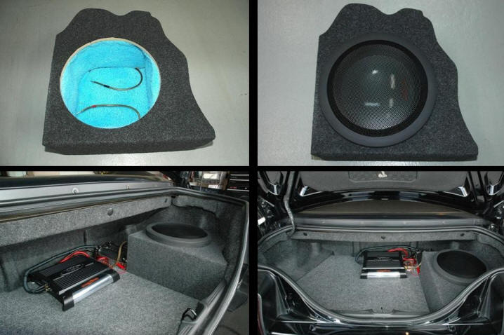
The panel in the upper left of the next composite shows the 12" subwoofer enclosure provided by an eBAY vendor who goes by the handle "customboxman" and runs a storefront that he calls Concept Enclosures. The box has been custom shaped to fit the contours of the trunk's right rear corner and has been constructed from high quality MDF and covered in trunk fabric that matches the color of the OEM material. I'm very pleased with this enclosure and strongly recommend Concept Enclosures to anyone in need of a subwoofer box. Tyler's enclosures are equipped with connector blocks for the speaker wires, but I added the internal 12-gauge wire and sound deadening material you see in the shot below. At the upper right of the composite, you see the Alpine SWR-1243D subwoofer that I selected for this project installed in the enclosure with a matching Alpine KTE-12WG expanded metal grille. The two bottom panels contain photos of all the subwoofer system components installed in Taz's trunk, hooked up, and ready to rock. Everything is easily removable to provide access to the spare tire if the need ever arises. Of course, the capacity of the Cobra's thimble-sized trunk has now been reduced to half a thimble, but Taz has always been strictly a fun machine, so I've never stowed much back there, anyway.
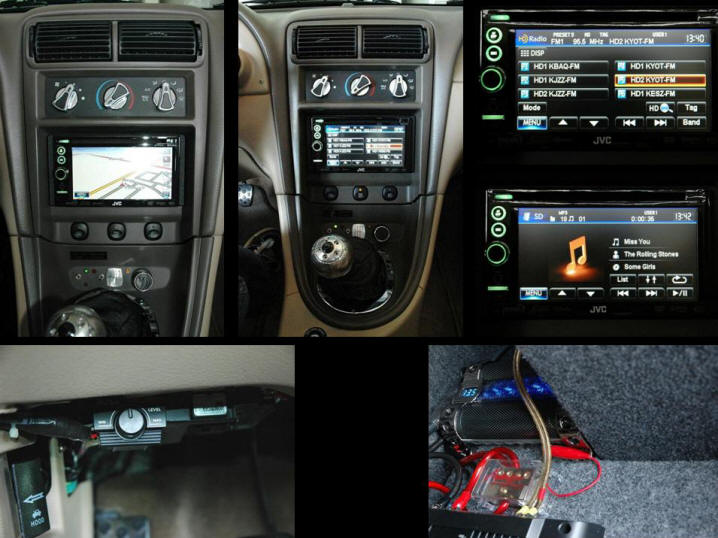
Editorial Comment: Although an amplifier's output power increases as the load it sees is reduced, distortion levels also rise as load impedance falls. The damping factor (an indication of the amplifier's control over the speaker) also ends up in the toilet when the impedance is minimal, resulting in a loss of musical definition. Considering these facts, only individuals without a clear understanding of these relationships would be lame enough to run a minimum impedance configuration. The Alpine SWR-1243D is equipped with dual voice coils, each of which presents a nominal 4-ohm load. Since the BOSS amp provides only a single, monaural speaker output, I needed to tie the sub's two voice coils together. If I wired them in parallel, the amp would see a net 2-ohm load, but wiring them in series would present the amp with an 8-ohm load. Despite the fact that BOSS Audio claims this amp is stable into loads as low as 1 ohm, I opted for the higher impedance configuration to obtain the best possible fidelity. Here are a few photos of the system in operation after I had installed the head unit in the center stack with a Metra #95-5026 double-DIN mounting kit that was designed specifically for the car. In the screen shot at the upper right of this composite, you can see a few of the HD radio stations transmitting in my area. We have well over a dozen. The shot below that one shows the unit's display during playback of an MP3 file on an SD card. In the bottom right photo, the numbers that you see displayed on the stiffening capacitor represent the voltage being delivered by Taz's electrical system with the engine idling. The red alligator clip partially visible in that same photo to is connected to the 10 ohm resistor that was provided for discharging and charging the capacitor whenever removing/reinstalling the subwoofer components. At the bottom left is a photo showing the location of the remote level control that was included with the subwoofer's amp.
If you'd like to have a PDF containing annotated copies of Taz's Navigation-Media project photos, as well as system wiring diagrams, just right click the link below and select the "Save Target As ..." or "Save Link As ..." option from the fly-out menu that will appear. This is a LARGE file (more than 6MB), so it may take a couple minutes to download, but that's still preferable to the delays you would otherwise encounter trying to view the file in place via the Internet. 2011 Navigation-Media project details (PDF) I currently have the in-dash unit's adjustable bandpass circuitry configured to switch between the Alpine subwoofer and the OEM mid/bass speakers at 100 Hz with a 12 dB per octave slope. The passive filters that I selected for the head unit's wiring harness provide 6 dB per octave crossovers between the system's midrange/bass speakers and midrange/tweeters at 500 Hz. Filters with different values would be required to shift this hinge point up or down, but the present configuration sounds just right to my ear. The sound quality is excellent with any type of music from classical to jazz to rock, so I'm very pleased with the way this project turned out. (While this is an admittedly biased and subjective opinion, don't dismiss it out of hand. It is offered by an individual who financed his postgraduate studies by catering to musicians, clubs, and left-wing lunatic fringe audiophiles with professional sound reinforcement equipment and esoteric audio gear.) In any event, don't let anybody persuade you that the only way to upgrade your Mach 460 system is to completely gut it and start over from scratch with all new components. If you approach the project logically, you can achieve genuinely stellar results changing only the pieces you want and leaving the others intact. You just need to be smarter than the car - and all the jokers telling you that it can't be done. If you decide that you'd like to modify your own Mach 460, you may find the following PDF a useful reference document. It contains the OEM system's wiring diagrams: Although the Cobra's audio system had been subjected to scant use prior to the installation of all this whiz-bang equipment, things have changed dramatically since then. Nowadays, most drives become very relaxed cruises as soon as I switch on the new audio system and begin enjoying my favorite music being reproduced with such superb sonic clarity. Even the antics of the idiots on the road around me don't irritate me nearly so much when I am immersed in the music, which makes the drive that much more enjoyable. In addition to outstanding sound quality, the JVC possesses a number features of which I am very fond and which contribute to this system's seeing much more use than the OEM setup ever did:
2013 Tweeter/Midrange Upgrades
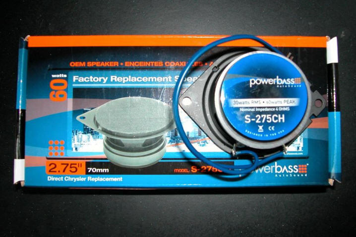
During the summer of 2013, I performed a nice little tweak to the overall tonal balance of Taz's media system that may be of interest to others, regardless of whether they're still running the factory Mach 460 head unit or an aftermarket unit connected to the OEM wiring and speakers. Although my system sounded great prior to this change, vocals had always been a touch edgy and string instruments, including acoustic guitars, tended to sound as if they had been strung with piano wire. After I installed the JVC head unit, I was able to minimize this edginess in the treble range with the unit's multi-band equalizer, but at the cost of reducing the overall output of the high frequencies. To address this issue, which had been a characteristic of the system ever since the Cobra was new, I’d been continually on the lookout for some alternative to the factory Mach 460 tweeter/midrange units. Due to the locations of the tweeter/midrange drivers and the system’s unconventional crossover frequencies, as well as the innate characteristics of the other speakers in the system, I had ruled out all of the aftermarket component tweeters. None of them can perform properly in this application, regardless of what some of the Great Unwashed on the forums would have you believe. Component tweeters are unable to handle the power levels delivered by the system throughout the midrange at higher volume levels, and none will adequately reproduce frequencies below about 1500 Hz. For a long time, it appeared I was never going to locate suitable replacements. But in 2013, I stumbled onto the PowerBass S-275CH speakers (shown below), which were billed as drop-in replacements for the optional Infinity audio systems in certain Chrysler/Jeep vehicles. They appeared to be the right size, possess broad enough frequency response, and have a more than adequate power handling capability. Besides all that, they were fairly inexpensive. This made trying a pair an essentially risk-free proposition – if I didn’t like them, I could just toss them out and reinstall the original Mach 460 speakers.
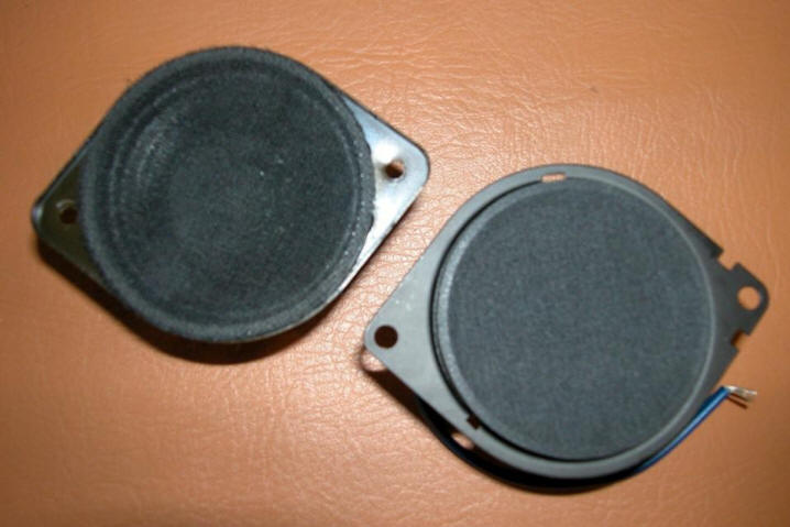
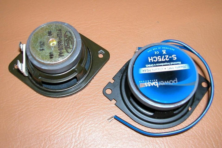
I bought two pair, because the Mach 460 uses the same tweeter/mid drivers in the back as well as the front of the car, but I have to date swapped out only the front ones. As of this writing, the back units will wait until the next time I pull the rear interior trim for some other purpose. The overall dimensions of the OEM Mach 460 driver (upper left in the photo below) are nearly identical to the S-275CH (lower right in the same photo). These are 2-3/4" drivers, which are practically impossible to find, and the opposing mounting ears make them scarcer than a virgin in a cathouse.
The photo below shows both speakers flipped over to reveal their backs. The S-275CH is fitted with a slightly larger magnet structure, but it still slips into the panel’s speaker cutout with no problem, and the S-275CH is actually a little shallower than the factory speaker, so there is no interference issue with the back of the panel. After the PowerBass speakers were installed, the Mach 460 covers snapped back on just as if the original speakers were still installed, so there's no visual indication that anything has been changed.
The S-275CH speakers were close to being drop-in replacements for their Mach 460 counterparts, but not quite. Their mounting hole spacing was 3-3/8” vs. 3” for the Machs. Not a problem – I just slotted the holes inward 1/4” on each side with my Dremel. Done deal. Also, as you can see in the photo above, the factory speakers are equipped with spade lugs, while the PowerBass speakers have pigtails. PowerBass supplies crimp connectors with the speakers, but I was reluctant to cut the spades off the wiring in the doors, just in case I didn’t like them and wanted to switch back to the OEM speakers. Instead, what I did was to remove the pigtails from their solder posts and replace them with male spades. Then, I plugged them in just like the originals and secured them using the OEM screws and original panel holes. After the installation, I emailed the folks at PowerBass to let them know they could significantly expand the market for these speakers to include the Ford Mach 460 and Mach 1000 systems (both use the same tweeter/mid drivers) by simply slotting the mounting holes on the frames inward toward the baskets to enable out-of-the-box 3” C-C mounting. I was a little surprised to receive a reply from the company’s Technical Director, who thanked me for the insight and informed me that he was going to see about having the factory implement my suggestion. He also said he would be sending me a PowerBass tee shirt. I thought that was very nice of him. It may not sound like much, but it’s a gesture that many companies would never make. As it turned out, the tonal quality of these PowerBass speakers was a great match for the rest of the system's components and exactly what I had been looking for. Following the swap, vocals and acoustic guitar sounded much more natural, and I can now actually feel the bow rosin when listening to classical stringed instruments. I'm very pleased with this little tweak.
Power Antenna
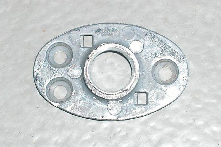
I never had any complaints with either the performance or the appearance of Taz's OEM antenna after I had shortened it to 18". It looked fine and worked perfectly. However, Taz is always covered when he isn't being driven, and his cover has no antenna grommet. This meant unscrewing and storing the mast after each drive and reinstalling it whenever prepping the Cobra for the next. This wasn't a great hardship, but it was a minor pain, so I had often thought of replacing the fixed mast with a power unit. However, none of the standard 33" models would do. First, they all resemble casting rods when extended, and, even more importantly, there was insufficient space between the fender mounting point and the liner in the wheel well to accommodate the drive assembly of a standard power antenna. Only a miniature version would be suitable, but it appeared that no such animal existed. Finally, in 2013, I discovered that Metra offered a power antenna equipped with a mast that was the same height when deployed as my shortened factory mast, the model 44-PW32. Perfect. I scored one of these kits in August, but waited until late October, after the summer heat had subsided, to tackle the installation. As soon as I began the project, I discovered that it would not be a simple swap. Although the Metra kit contained an assortment of bases, none would be suitable for use with the Cobra. The OEM base had been secured with three screws that had been threaded into nutserts in the top of the fender, and the spacing of these nutserts was such that none of the Metra bases would conceal them. The logical alternative was to reuse the factory base, which I did. However, considerable meatball surgery was required. The factory base consists of three separate parts, top and bottom plastic pieces with a metal plate sandwiched in between them. Both plastic parts snap onto the metal plate. Of the three, only the bottom plastic piece required no modification, but the metal plate was the one that presented the real challenge. In order to make it work with the Metra antenna, I needed to completely gut it and hog out its center tube. I also had to remove the portion of this tube that extended beneath the fender. Below is a photo of the metal piece after I had modified it as required. Sorry, no "before" photo of this part, but the second photo below shows the pieces that I needed to remove prior to hogging out the shortened center tube.
To accommodate the Metra and an insulating sleeve that I added to prevent the new antenna from grounding out on the chassis, I needed to increase the inside diameter of the metal tube quite a bit to 0.60". The following shot depicts the modified part and plastic baseplate secured to the car's fender, ready for the power antenna.
Next up was the actual antenna installation. The photo below will give you an idea of just how tight the fit was. The flex loom visible in that shot below the antenna's bottom bracket isn't factory. It was added previously as part of another project. The drain tube supplied with the kit had not yet been installed, but its mounting nipple is visible at the bottom center of the mast cable's reel housing.
In the above photo, you can also see the body grommet supplied with the Metra kit for the antenna and power cables. This grommet perfectly fit the hole that had originally contained the grommet for the factory antenna. However, the kit's mounting spacers required some modification in order for the tip of the mast to sit flush with the top mounting ring when retracted, because the OEM base is a bit taller than the Metra bases. After mounting the antenna, I routed the RF cable and power wires to the head unit and connected them. The two photos below show the finished project with the antenna retracted and extended.
|